bn
Blend4Web: Beginner's Guide. Chapter 7: Labyrinth Of Logic
2016-12-26
IF…THEN…ELSE… wait, wait, don’t close this tutorial! You won’t need any text editor, or compiler, or any other things that bearded programmers use. The developers of Blend4Web have made a splendid gift for all artists which is the visual logic editor.
You only need a mouse and a little bit of savviness, and your project will become truly interactive. And about those mysterious words at the start of the page, well, they really are from the world of programming, but I’ll let you in on a little secret: our program will be perfectly fine without them.
Preparing for Work
Blender is a very powerful solution for creating and animating 3D models. Everything you’ve learned from my tutorials is but a tip of the iceberg. All this time we have been studying the tools we need to create a presentation, and now it is time to make the acquaintance of another one.
Blender provides a unique editor that allows users to construct materials, textures or scene compositions from specific logic blocks known as nodes. On a practical level, it looks like placing separate functions (represented by nodes) in a specific order and establishing links between them. In the case of Blend4Web, the very same editor is used for creating scene logic.
Blender actually features a template for working with the node editor, and it is called Compositing. If you select it, you will see a new, unfamiliar window shown in the Figure 1.

Figure 1
You have to prepare some things in advance to use logic nodes in your scene. First, switch the node editor to logic mode. This is done by clicking a certain button on the window’s panel. It is marked red on the figure.
Second, you have to create a node tree. This is a complex unit that encapsulates all of the logic used in our presentation. Press the New button to create a new tree. By default, this tree is simply named NodeTree, but, of course, you can rename it.
And third, you have to specify your new tree in the Blend4Web settings. To do this, switch to the Properties window, open the Scene tab and activate the Logic Editor option. Then select the tree from the list below. However, if the tree is not on the list, press the refresh button beside of the menu.
That’s all. Now, you are ready to program.
The Simplest Pipeline
Working with a program should start with setting goals. You have to first ask yourself what your presentation will do, and only afterwards decide how this can be done. Do not rush to start working if you don’t clearly understand the purpose of the work!
So, our educational application will be able to:
Demonstrate the model by rotating it.
Switch the color of the frame if specific buttons in the applications are clicked.
“Turn on” the smartphone and show an image on its screen.
And now, let’s get to work...
Blend4Web features a massive set of logic nodes that can be found in the Add menu. All of them are separated into categories.
Every logic tree should always start with the Entry Point node from the Control Flow category. It acts as a starting point for your logic. What’s interesting is that Blend4Web allows you to use several logic threads with separate Entry Point nodes. This can be used for executing multiple tasks in parallel, yet in our case one thread is enough.
Add another node to the project: the Switch Select node from the Control Flow
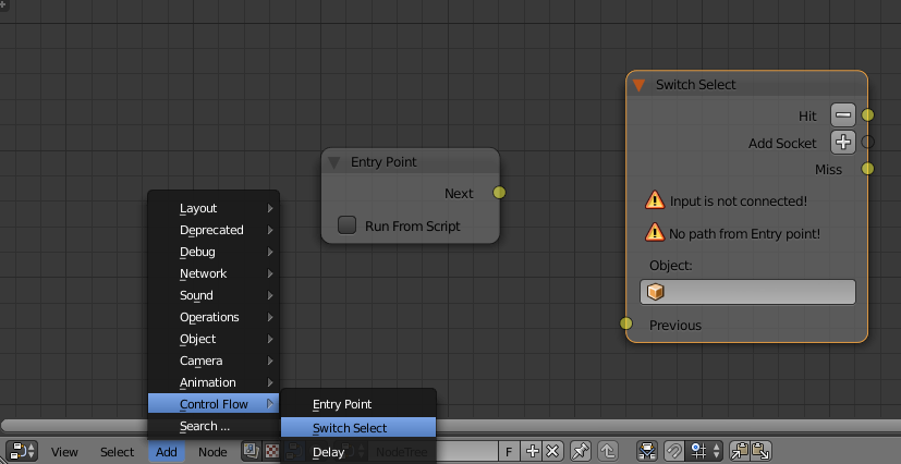
Figure 2
Before we start talking about what the Switch Select node is for, let’s try to link the two nodes in one thread.
Take notice of yellow circles at the sides of the nodes. These are the junction points that are used for connecting the nodes. On the left side of a node, we find the input socket, while the output socket can be found on the right. As an Entry Point always acts as a first node in the thread, it only has the Next socket.
Select the Next socket of the Entry Point node by using the left button of your mouse. A conductor line will appear. Move it to the Previous socket of the Switch Select node while holding down the left mouse button. When your mouse is over the socket, release the button. This is how links between nodes are established (fig. 3).
You can break this link by separating the conductor line from the Next socket or by holding down the CTRL key and guiding the mouse cursor above the link you don’t need.

Figure 3
The Switch Select node is the most frequently used node in the entire set. Using it, you can trace user-selected objects and transfer control to another node. To do this, you have to select an object you need from the Object menu. This should be the frame of the smartphone. In my example, it is titled Phone.
Blend4Web features a multitude of templates that make creating a presentation significantly easier. One of them is an option to automatically outline an object when it is selected. To enable this function, select the object you need (Phone), open the Object panel in the Properties window and go to the Selection and Outlining tab. Set the options as shown in Figure 4.

Figure 4
You can set the color for outlining in the general Blend4Web settings (fig. 5).

Figure 5
So, let us reason. Control is passed from the Entry Point to the Switch Select. Then, the program is waiting for a click of the mouse, and if the Phone object was clicked, control is passed to the next node which is connected to the Hit output (see the figure above).
But there is one detail we should keep in mind. The Switch Select node waits for a user’s actions and then it either passes the control or simply ceases to work. So, we better “tell” the node what it has to do in case a wrong object is selected. Look at Figure 5. The Switch Select node has another output by the name of Miss. It is here where control is passed if a wrong object is selected. Because of this, we have to “return” this output to the input of the Switch Select node.
Add two Reroute node objects from the Layout category to the scene. These are auxiliary nodes that are often used to make links between nodes easier to create and understand. Look at the figure below and set everything as shown there.

Figure 6
Here, we also have a new node called Stop Animation (the Animation category). Its purpose is to turn off the animation of an object set in the Object field. We studied creating animations in Blender in the previous lesson, and we created constant spin for an Empty object. Set this specific object in the Stop Animation node.
Now our logic thread is able to recognize a mouse click on the phone model and to stop the spin animation.
Our current tasks are the following: to move the holder from the field of view, turn the phone so it faces the camera and move it a little closer.
Create a separate animation of moving the holder off the screen, for example, down. Use Location keys for this.
Don’t forget that every lesson is fit with source files so you can see how it is done there.
The animation of the holder should not start automatically with the application. Here, we will use the Play Animation node from the Animation group (fig. 7).

Figure 7
The Play Animation node starts an animation of the object set in the Object field. The Anim Name field is for setting the name of an animation, if an object has more than one. In our case, the holder only has one animation, so leave this field empty.
The Behavior menu is used to define what happens when the animation is complete. Set it to Finish Stop. Last is Do Not Wait which makes the node pass control to the next node right away instead of waiting until animation is finished.
So, now our logic thread can register mouse clicks, stop the turning of the phone and move the holder away from the screen. But we still have to turn the phone right to the camera.
There is an excellent node in the set of logic blocks, which can change the current parameters of an object, such as Location, Rotation or Scale. Essentially, you can animate objects using this node.
Meet the Transform Object node.

Figure 8
This is a very powerful tool for creating animations using node logic! As usual, you have to specify the object it will control. In our case, it is the frame of the phone.
We then have to set the end parameters of the object’s transformation. You can copy the coordinates of the phone from the Transform panel (the N hot key), as we don’t need to change them. Instead, we are interested in the Rotation and Scale parameters.
In our test scene, we should set the Rotation of the phone by all axes to zero in order to make it face the camera. In your scene, this might be different. Try to experiment, to turn the object to the position you like, and then copy the rotation parameters to the node.
The Scale parameter controls the size of the object. It is set to 1 by default and thus does not change anything. I myself set it to 1.5 as this value turned out to be the most optimal one.
The Duration parameter sets the length (in seconds) of the animation. About two seconds should be enough.
And here is the complete logic tree that we have made in this lesson (fig. 9).

Figure 9
It only took us five nodes to make our scene interactive. As you can see, it’s easy to program in Blend4Web. Even if you are not familiar with the subject of programming, the visual logic editor gives you the opportunity to create presentations filled with action.
Updated source files can be found in the Blend4Web SDK starting from version 17.01 (this applies to both CE and PRO versions). The files are located in the blend4web/blender/tutorials/basic/for_beginners folder.