Striped Shader Part 1
2014-04-10
Often it might be useful to use strips for procedural texturing. The Blender's node editor is a convenient tool for creating such things. A Blender artist can easily publish his resulting scenes to the web because the Blend4Web framework natively supports node materials.
For the beginning lets consider a simple example - a single strip with hard edges. Lets add a plane.
Please note that this article is intended for experienced Blender artists. It's supposed that the reader is familiar with the Blender user interface and has mastered the basic techniques.
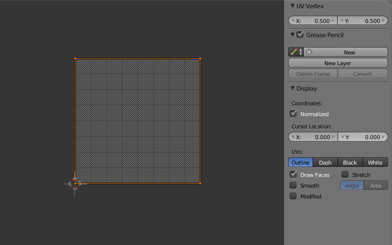
1) Lets do some preparations. Unwrap the plane to get a UV layer which follows the plane from 0 to 1 by both axes.
 Create a material and activate the nodes.
2) Lets look at the nodes. In this example we won't bother with lighting so there is no a Material node.
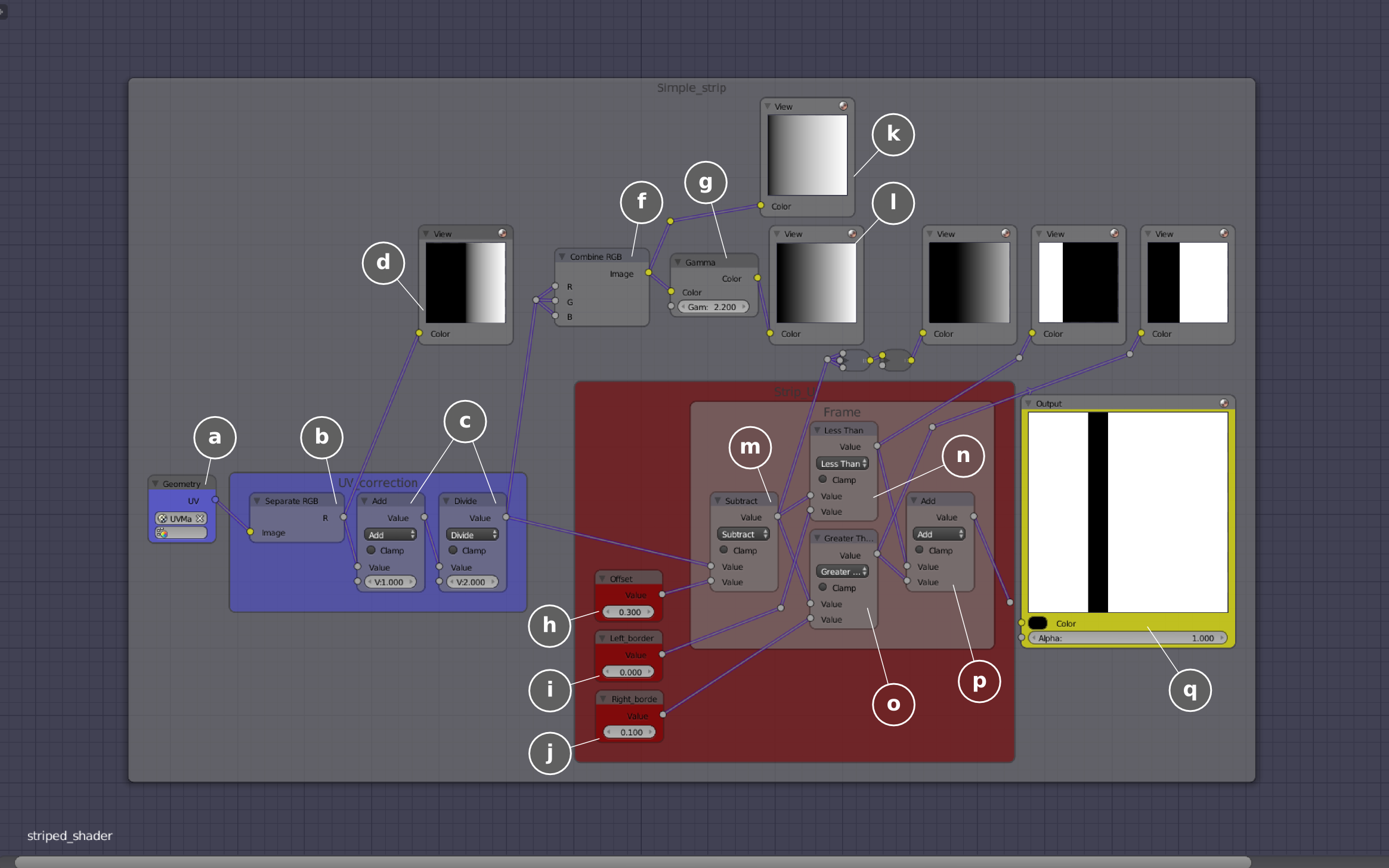
3) To make a strip we need some input data. The node tree starts at (a) where the Geometry node is placed. In my experience it's better to hide unused node sockets. Lets take the UV data (а) and separate a single component U or V (b) and view it (d). As we see a monochrome gradient is shifted to the right. So before using the UV data we need to slightly modify the UV space. The reason is that in a Geometry node (for the internal renderer) the UV space is scaled by two times and shifted by -1. Therefore we need to reconstruct the UV space by carrying out operations in the reverse order (c). To do so we add 1 and divide by 2.
To visualize the UV-space properly we need to use gamma-correction with a 2.2 factor (g). The reason of this is that calculations are performed in a linear space but the picture is displayed in an sRGB space.
4) Because all gradients are transformed into sharp black/white transitions in the shader, the resulting Output node receives data without gamma-correction which is used only for intermediate visualizations (l). An active (i.e. a selected) node will be the resulting one (q).
5) The Value node which is named Offset defines the strip mixing step along the horizontal direction (h).
6) This offset is calculated by the Subtract node (m).
7) Then we make a fork and separate the negative values using the Less Than node (n). By changing values from 0 to -1 we can adjust the left boundary of the strip. This parameter is controlled by the Value node which is named Left Border (i).
8) The Greater Than node selects values bigger than 0.1 (o). By changing values from 0.1 to 1 we can adjust the right boundary of the strip. This parameter is controlled by the Value node which is named Right Border (j).
9) Finally we sum the results after fork (p) and get the strip (q).
The Blend4Web engine (contrary to Blender) doesn't support implicit conversion of data types. Therefore if we want to get predictable results we must follow simple rules. In Blender there are three data types: integer and float numbers (gray sockets), RGB or RGBA colors (yellow sockets), XY or XYZ vectors (purple sockets). We must connect only the compatible sockets. A conversion example is demonstrated on the shader scheme (f). Of course this conversion makes sense only if such a chain goes to a final Output node (q).
It is not necessary to use UV coordinates as input data - e.g. global object coordinates can be used as well - this depends on the task.
In the beginning of this article there is an interactive frame with the resulting shader applied to some different objects.
The described shader was initially created for the Cycles renderer and then reworked a bit to fit Blend4Web.
You can find the source blend file in the following directory: blend4web/blender/tutorials/basic/striped_shader_1/.
To be continued...
Changelog
[2014-04-10] Initial release.
[2015-09-04] The text and illustrations have been updated; also a screenshot showing the special node RGB_TO_LINEAR has been deleted, because both Blender and Blend4Web now support the Gamma node.
[2017-01-12] Fixed incorrect/broken links.